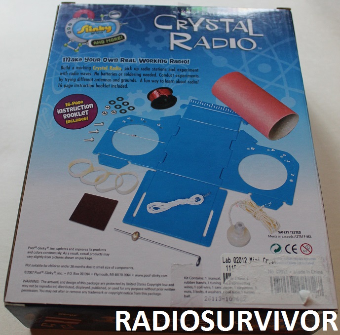
This week my dad and I made a second attempt at building a crystal radio using one of the kits that I got for Christmas. Readers might recall that back in December we made a radio using the Elenco Crystal Radio Kit. This time around we tried out the Slinky Experiment #151 Crystal Radio Kit.

Slinky Crystal Radio Kit. Photo: J. Waits
Initially my dad had been less interested in the Slinky kit because it did not include a pre-wound copper coil (which the Elenco kit had), but we trudged on anyway, hoping that this time around we would successfully build a working radio. The kit, which is recommended for ages 8 and up, promises that it will allow one to “make your own real working radio without batteries!”
Back of Slinky Crystal Radio kit package. Photo: J. Waits
After examining all of the pieces, we decided to start assembling the plastic radio base first so that we knew what we were dealing with before we started preparing the tuning coil. It was pretty simple to bend the panels to form the radio’s base, although the plastic looked a little bit warped, so things weren’t exactly fitting together as squarely as they should. My dad wanted to do this part first so that he could ascertain how much clearance we needed to leave on the edges of the tuning coil, so that it would fit into the base.
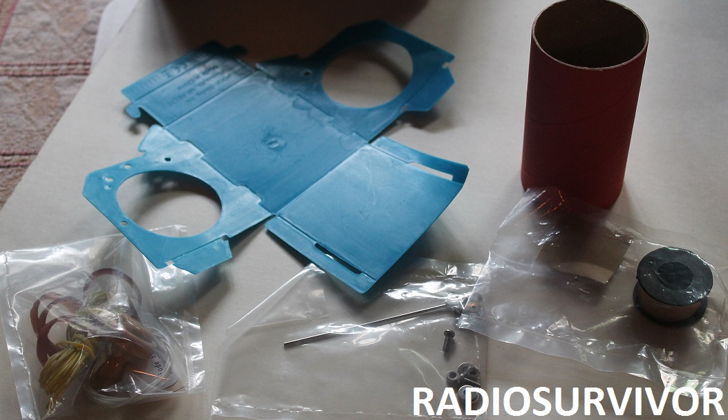
Slinky Crystal Radio Kit parts. Photo: J. Waits
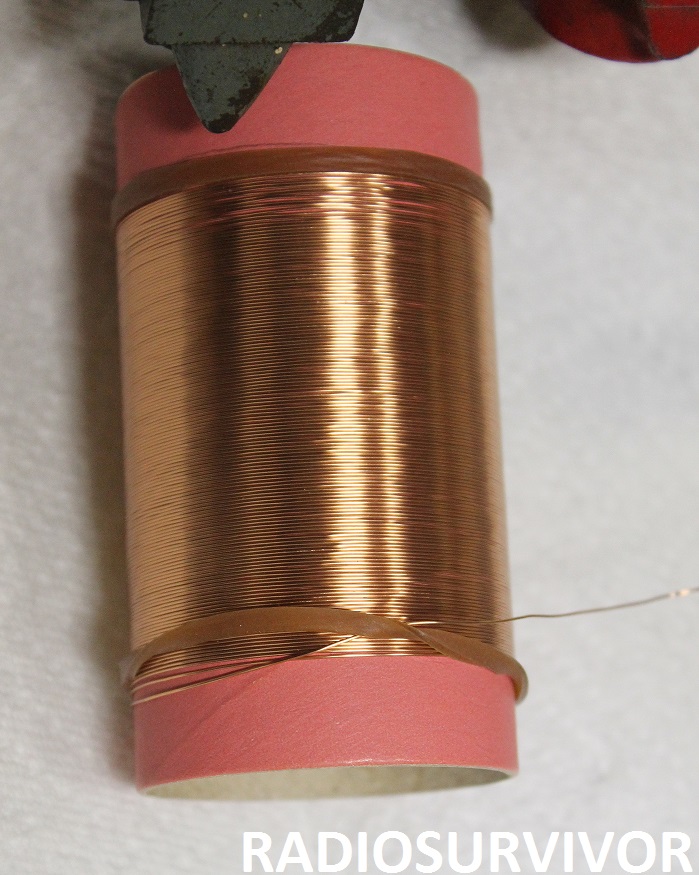
After partially assembling the base, we started the most arduous part of the project: winding copper wire onto a cardboard tube to create the tuning coil. The instructions state, “adult supervision is advisable for this task. Winding the coil must be done very carefully and precisely, or your radio will not work.”
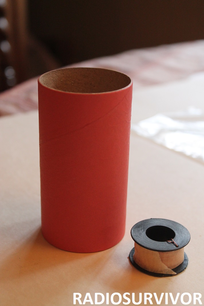
Paper tube and spool of copper wire. Photo: J. Waits
We placed a rubber band (included with the kit) about half an inch from the edge of a cardboard tube (similar to a sturdier toilet paper tube). Although the instructions didn’t mention it, my dad thought it would be a good idea to place a second rubber band on the other end of the tube BEFORE we started to wind the wire. We figured out the amount of empty space required on each end of the tube when we tried inserting the tube into the plastic base and then placed the rubber bands accordingly.
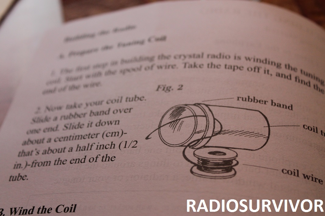
Slinky Crystal Radio instructions. Photo: J. Waits
The kit included a small bobbin-like spool of copper wire. That wire needs to be carefully wound around the paper tube, without any overlap. In order to do this more precisely, the instructions recommended attaching the spool onto a pencil which is secured between two heavy stacks of books. The idea is that this can secure the spool so that one can slowly wind the wire onto the tube.
Attaching the spool of copper to a dowel. Photo: J. Waits
My dad was skeptical about this method (you might recall that he’s an engineer) and suggested that we instead set up two clamps on his workbench in the garage. He grabbed a dowel rather than a pencil (telling me that pencils aren’t the best choice since they are typically hexagonal), slipped the spool over the dowel and then clamped it on both sides.
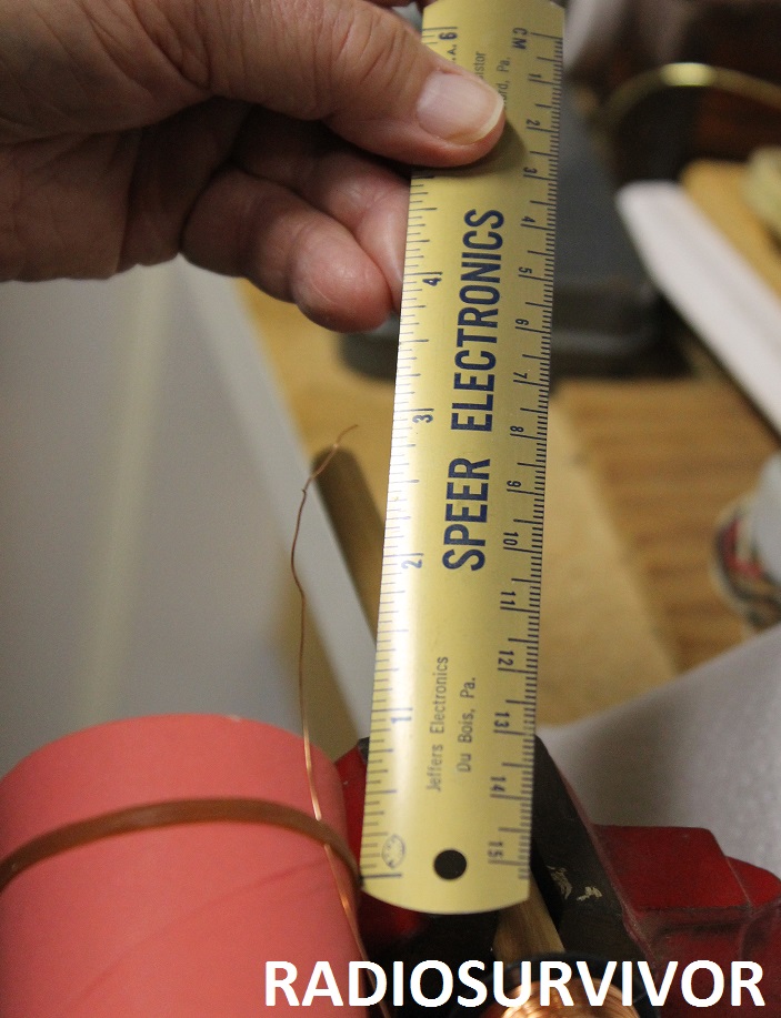
Measuring 3 inches of wire off the end of the tuning coil. Photo: J. Waits
Satisfied that the coil could move freely, but not too fast, we began the process of winding copper wire onto the paper tube. My dad held the tube, keeping his thumb atop the wire as he wound it. The first rubber band is used to secure the edge of the wire so that it doesn’t come off.
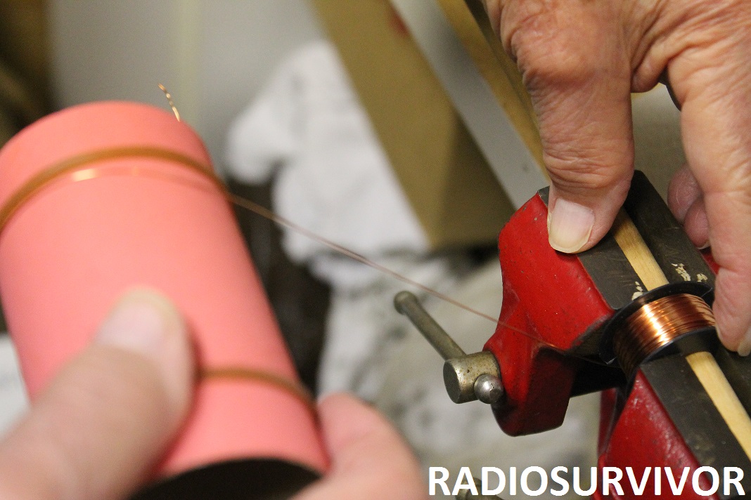
Starting to wind the tuning coil. Photo: J. Waits
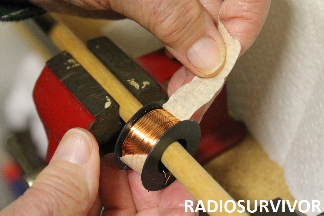
Although the instructions aren’t explicit about this, the included drawings show that around 3 inches of wire should be left loose off of the coil. I kept a fingertip (actually a fingernail) atop the spool so that we could slowly unwind it without unloosening all of the wire.
Nearly done winding the copper wire onto the paper tube. Photo: J. Waits
Make sure you have plenty of light and patience as you start the coil winding part of this project, as it took us at least 30 minutes to complete. When we reached the end of the wire, we rolled the second rubber band over the edge of the coiled wire, leaving about 3 inches of wire loose at the end.
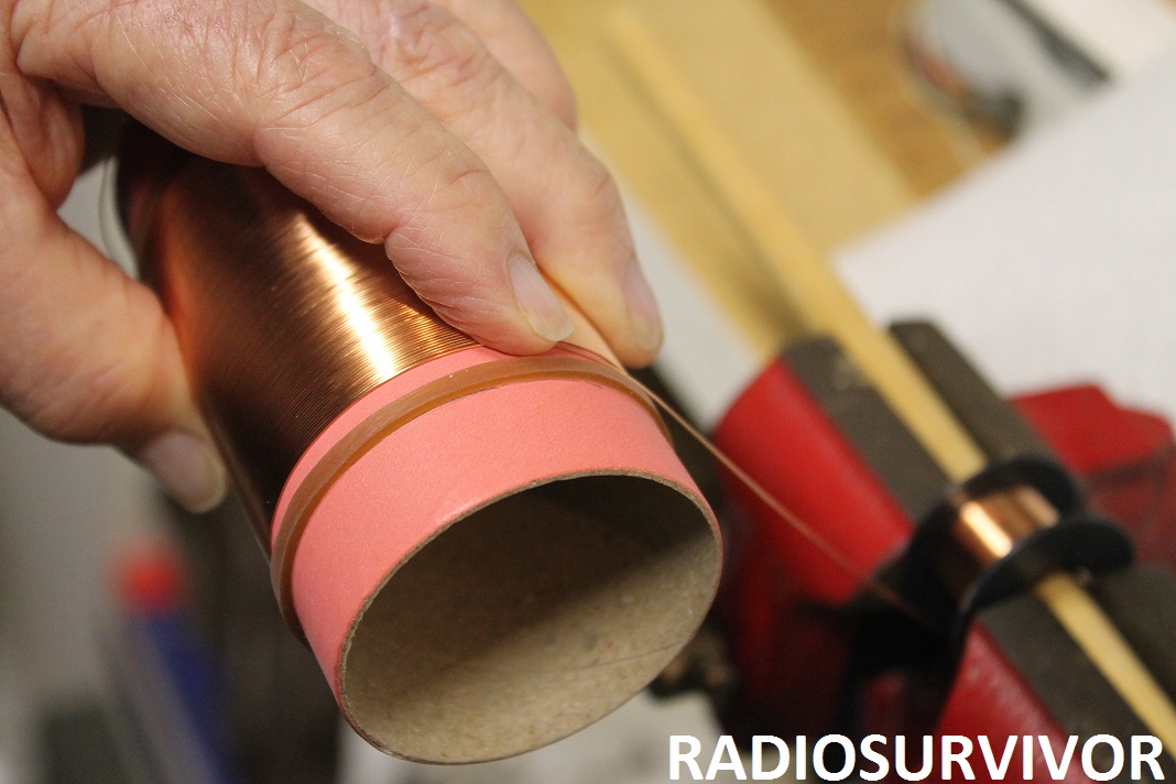
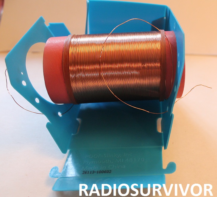
Completed tuning coil. Photo: J. Waits
As my dad wound the copper coil, he got into a rhythm, telling me that it got easier as he went along. We were pretty satisfied with the winding and didn’t see much overlap or gaps in the wires, especially towards the end of the coil.
Putting the tuning coil into the plastic radio base. Photo: J. Waits
After winding the tuning coil, we inserted it into the blue plastic base that we had partially constructed earlier. We then inserted coil wire through labeled holes in the base. About an inch of one end of the wire then had to be sanded so that plastic insulation material could be removed.
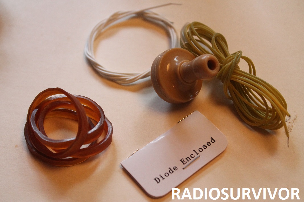
Crystal Radio Kit parts (rubber bands, connecting wires, earphone, diode) . Photo: J. Waits
Following this step, we prepared the earphone, diode and connecting wires. I created small loops at the end of the diode wires and connecting wires by winding them around the tip of a pencil. At this point we were back working inside the house in a dimly lit room and I realized that good light (and good vision) was a necessity for this part of the project.
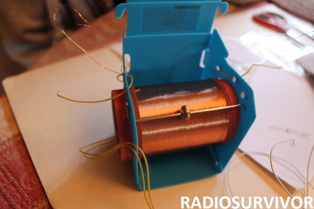
Getting the tuning bar and other components in place. J. Waits
The remaining steps were delineated pretty clearly in the instructions. I needed to put specific wires through specific holes in the blue plastic base and then had to slide a metal tuning rod through a hole in the base. After slipping the small metal tuning ball onto the rod, we were ready to start making connections with all of the wires. I have to note (as was the case with the last kit that we tried), that we needed to use a wire stripper (luckily my dad has one) to remove the plastic covering from the ends of many of the wires, as there often wasn’t enough bare wire to work with.
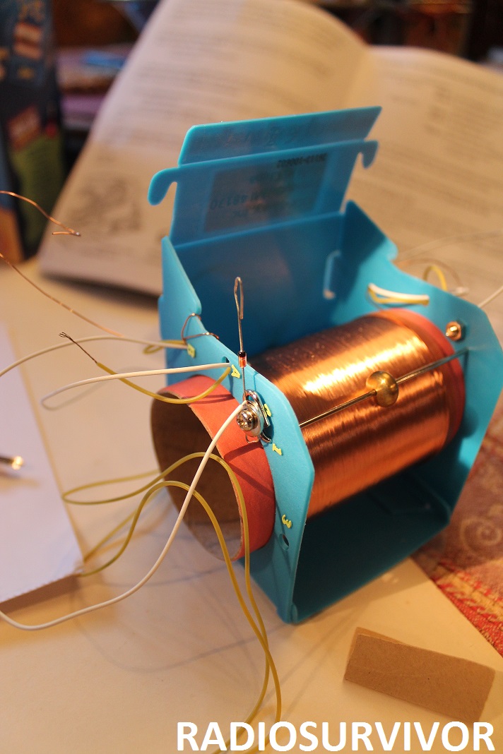
Attaching the diode. Note the screws. Photo: J. Waits
While the previous radio kit that we assembled used pronged brass paper fasteners to make the connections, the Slinky kit used a sturdier bolt, washer, and nut combination. I carefully followed the instructions and slipped the looped ends of various wires onto a bolt with a washer on it. After securing the connections with a second washer, I connected the whole assembly into one of the holes on the radio base and secured it with a nut. Wires often slipped off while I was doing this work and I found myself getting frustrated, especially since I was having trouble seeing and also because it can be challenging working with such tiny pieces.

Diode is now connected. Photo: J. Waits
In the process of making these connections we attached the diode to the outside of the plastic base, looping its wire with a connecting wire on one side and with an earphone wire on the other side. After making a total of 5 different connections with various wires and components, we closed up the base of the radio.
The final task was to sand off a strip of the copper tuning wire that would be directly below the tuning ball so that the ball could make contact with bare wire and hopefully pick up a radio signal. The instructions said to rub the tuning ball along the wire in order to make a light mark. Although I tried that, I never saw a mark. Instead, I rolled the tube a bit and sanded the wire in the place where it seemed the tuning ball would hit. I’d recommend folding the sandpaper and doing the sanding with the sharp folded part of the paper.
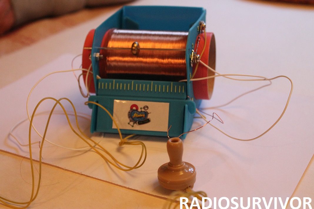
Finished Slinky Crystal Radio. Photo: J. Waits
It was now the moment of truth. We brought the radio to a cold water faucet and touched a connecting wire to the faucet while I held the other wire in my hand. We moved the tuning ball across the copper coil and…
…heard nothing in our earphone.
After trying several other faucets inside and outside, we still didn’t hear anything. One challenge was that the remaining connecting wires were very short, which made it difficult to hold everything in place while trying to listen. If we had a longer wire, we could have rigged up a better antenna. Additionally, I’m not entirely sure if I sanded enough insulation off of the copper wire.
While doing the project, my dad talked again about soldering, saying that the results would be more reliable if we had soldered the connections.
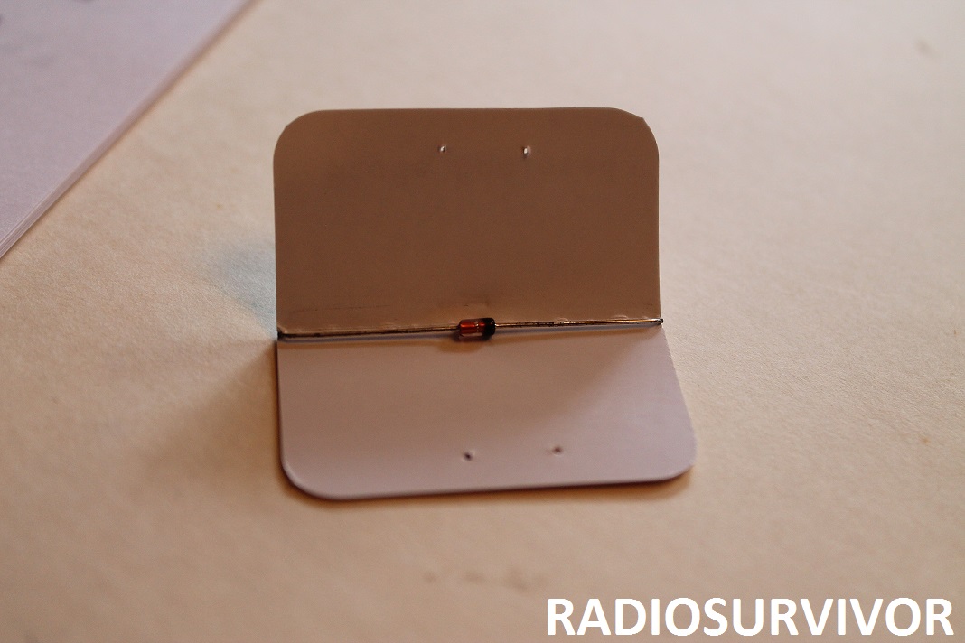
Diode. Photo: J. Waits
We are determined to eventually make a working AM radio, so I did some investigation after this 2nd failed attempt. Online reviews for the Slinky kit were dismal and I only found a few people who actually got it to work. As with all crystal radios, another important factor is proximity to an AM transmitter, so that could be part of the problem as well. Several reviewers said that the diodes in their kits were defective or were of the wrong type. My dad had actually noted at the beginning of the project that he thought the copper in our diode looked shorted.
Ultimately, I think Slinky’s labeling of the project as an “experiment” is something to keep in mind. I started the project not knowing if the radio would actually work and in the process learned a bit more about what to look for in future radio projects. I’ve already got my eye on a kit that requires soldering. Stay tuned…